#Arduino relay module tutorial
Explore tagged Tumblr posts
Visit Tumblr Blog
Explore Tumblr blogs with no restrictions, modern design and the best experience.
Last Seen Tumblr Blogs


Fun Fact
After the announcement of the deal with Yahoo!, there were 170K signatures of unhappy Tumblr users petitioning to prevent the sale in 2013.
Video
youtube
DIY Temperature Controller for Molding Systems | Arduino Tutorial
#youtube#DIY#Arduino Tutorial#Temperature Controller#Molding Systems#Injection Molding#Arduino Nano#Membrane Keypad#LCD#Relay Module#Max6675 Module#Thermocouple#Plastic Molding#Electronics Tutorial#Maker Community#Plastic Injection Molding#Arduino#Hot Nozzle#Molding Process#MAX6675#LCD Display
1 note
·
View note
Text
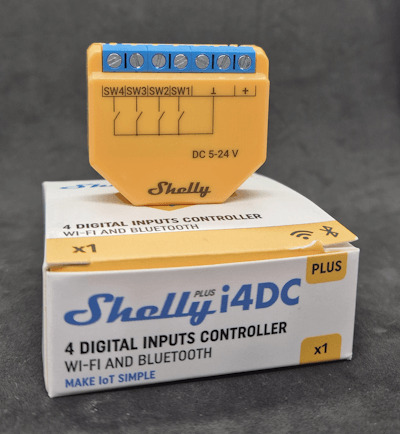
Smarthome ohne Spionage: ESP32 und Shelly i4 DC als drahtlose Steuerung für dein Zuhause
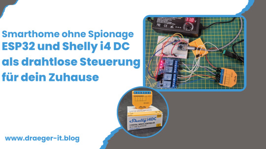
Ich möchte dir eine drahtlose Steuerung mit ESP32 und einem Shelly i4 DC vorstellen, mit der du Smart-Home-Geräte komfortabel bedienen kannst. Viele setzen dabei auf Sprachassistenten wie Alexa oder Google Assistant – doch nicht jeder möchte sich einen „Spion“ ins Haus holen, der dauerhaft zuhört. Eine Funksteuerung mit ESP32 und Shelly i4 DC ist eine sichere, lokale und flexible Alternative, die ohne Cloud oder Internet funktioniert. https://youtu.be/oVJkW2YQ7To Den Shelly i4 DC habe ich bereits ausführlich in meinem Beitrag "Smarter Schalter für Gleichspannung: Der Shelly i4 DC im Detail" vorgestellt. Zudem findest du auf meinem Blog bereits zahlreiche Beiträge zum ESP32, da dieser Mikrocontroller eine perfekte Grundlage für smarte DIY-Projekte bietet. Mit einer 4-Tasten-Funkfernbedienung und dem Shelly i4 DC lassen sich bis zu vier verschiedene Aktionen ausführen – von der Lichtsteuerung bis zum Öffnen des Garagentors. In diesem Beitrag zeige ich dir, wie du diese praktische und datenschutzfreundliche Smart-Home-Lösung umsetzt.

Schaltung - Shelly i4 DC mit Relais Modul und ESP32-S3-Zero
Warum diese Schaltung, wenn Shelly auch per WebHook steuerbar ist?
Theoretisch kann man jeden Shelly direkt über WebHooks steuern, indem man HTTP-Requests an das Gerät sendet. Damit ließen sich Shelly-Produkte ganz ohne zusätzliche Hardware per WLAN in ein Smart-Home-System einbinden. Aber: Was, wenn du eine unabhängige, einfache Lösung suchst? Ich möchte dir hier eine alternative Schaltung zeigen, mit der du Geräte in deinem Smart Home über eine klassische Funkfernbedienung (433 MHz) bedienen kannst – ohne WLAN, Cloud oder App. Diese Lösung ist besonders dann interessant, wenn du: ✔ Geräte lokal und offline steuern möchtest, ohne auf eine Internetverbindung angewiesen zu sein. ✔ Eine einfache Fernsteuerung bevorzugst, die keine App oder komplizierte Einrichtung erfordert. ✔ Ein bestehendes Funk-Setup mit 433 MHz Fernbedienungen nutzt und dieses mit Shelly kombinieren möchtest. Dazu setze ich einen ESP32 mit einem 433 MHz Funkempfänger und einem 4-fach Relais-Modul ein. Die Relais steuern die Eingänge des Shelly i4 DC, sodass du mit einer drahtlosen 4-Tasten-Fernbedienung bis zu vier verschiedene Smart-Home-Aktionen auslösen kannst.
Die richtige Funkfernbedienung wählen
Wer eine passende 4-Tasten-Funkfernbedienung sucht, findet auf AliExpress und eBay eine große Auswahl an Modellen. Wichtig ist, auf die Frequenz zu achten: In Deutschland sind 433 MHz-Modelle erlaubt und weit verbreitet, während 333 MHz-Fernbedienungen hier nicht genutzt werden dürfen. Dies ergibt sich aus dem Frequenzplan der Bundesnetzagentur, der die zulässigen Funkfrequenzen regelt. Achte daher beim Kauf darauf, dass das gewählte Modell den gesetzlichen Vorgaben entspricht. Das 433 MHz Funksender Kit für den Arduino habe ich dir bereits im Beitrag Arduino Tutorial 37: 433 MHz Sender & Empfänger
Benötigte Hardware für das Projekt
Für dieses Projekt kommen folgende Hardware-Komponenten zum Einsatz: - ESP32-S3 Super Mini von Waveshare* – ein leistungsstarker Mikrocontroller mit WLAN- und Bluetooth-Funktionalität - Shelly i4 DC* – ein smarter Schalter mit vier digitalen Eingängen für Gleichspannung - 433 MHz Funkempfänger* – zur drahtlosen Signalübertragung von der Fernbedienung an den ESP32 - 433 MHz Funksender* – ermöglicht das Senden von Signalen an andere Geräte (günstig im 2er-Set erhältlich) - vierfach-Relais-Modul* – dient zur galvanischen Trennung und ermöglicht das Schalten der Eingänge am Shelly i4 DC - diverse Breadboardkabel & 400-Pin Breadboard* – für eine einfache Verdrahtung ohne Löten - ein USB-Netzteil* - wird für die Stromversorgung des Mikrocontrollers und des Shellys benötigt - ein Power-Supply-Modul für Breadboard* - über dieses Modul kann man 5V & 3.3V abgreifen um unter anderem den Shelly zu betreiben Hinweis von mir: Die mit einem Sternchen (*) markierten Links sind Affiliate-Links. Wenn du über diese Links einkaufst, erhalte ich eine kleine Provision, die dazu beiträgt, diesen Blog zu unterstützen. Der Preis für dich bleibt dabei unverändert. Vielen Dank für deine Unterstützung! Stromversorgung Sowohl der ESP32-S3 Super Mini als auch der Shelly i4 DC benötigen eine Stromquelle. Hier eignet sich theoretisch ein einfaches USB-Netzteil*, das sich leicht zweckentfremden lässt. Da der Shelly i4 DC bereits ab 5V betrieben werden kann und weniger als 1W Leistungsaufnahme hat, reicht ein handelsübliches Netzteil vollkommen aus.
Aufbau der Schaltung - Shelly i4 DC via Funkfernbedienung über ESP32 steuern
Nachfolgend die kleine Schaltung im Schaubild wie die Komponenten zusammenarbeiten.
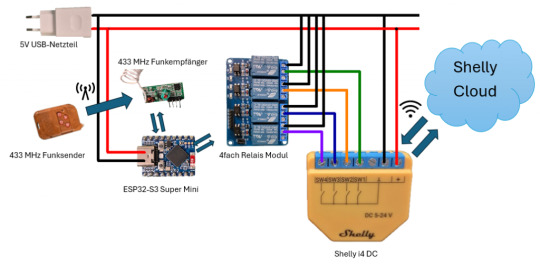
Schaltung - 433MHz Remotecontroll und Shelly i4 DC KomponenteESP32-S3 Mini4fach Relais ModulVCC5VGNDGNDIN1GP2IN2GP3IN3GP4IN4GP5433 MHz FunkempfängerVCC5VGNDGNDDATAGP1 Anschlussklemme des Relais Ein 4-fach Relaismodul bietet für jeden Kanal eine dreipolige Anschlussklemme, bestehend aus: - Links (NC - Normally Closed) → Ausgang aktiv, wenn die Relais-LED AUS ist - Mitte (COM - Common) → Gemeinsamer Anschluss für den Schaltkreis - Rechts (NO - Normally Open) → Ausgang aktiv, wenn die Relais-LED AN ist
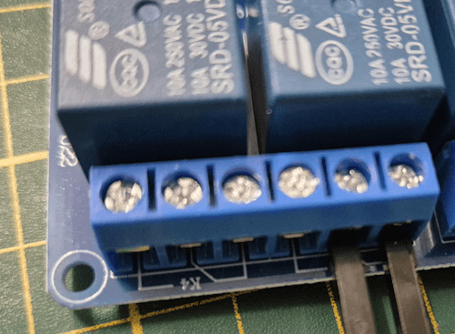
Relais Modul-Anschlussklemme Verdrahtung mit dem Shelly i4 DC - Der GND-Anschluss des Shelly i4 DC wird mit dem rechten (GND) Anschluss der Relaisklemme verbunden. - Die Eingänge des Shelly i4 DC können entweder über den mittleren (NO) oder linken (NC) Kontakt mit dem Relais verbunden werden, je nach gewünschtem Schaltverhalten: - NO (Normally Open): Eingang wird aktiv, wenn das Relais anzieht (LED leuchtet). - NC (Normally Closed): Eingang wird aktiv, wenn das Relais nicht angezogen ist (LED aus). Pinout des ESP32-S3 Mini Nachfolgend das Pinout des ESP32-S3-Zero von Waveshare.

Aufbau - ESP32-S3-Zero
Programmieren - drahtlose Steuerung eines Shelly i4 DC am ESP32
fertiges Programm Programm: drahtlose Steuerung eines Shelly i4 DC über ESP32Herunterladen Quellcode /* Projekt: Smarthome ohne Spionage – Funksteuerung für den Shelly i4 DC mit ESP32 Autor: Stefan Draeger Blog: https://draeger-it.blog Beitrag: https://draeger-it.blog/smarthome-ohne-spionage-esp32-und-shelly-i4-dc-als-drahtlose-steuerung-fuer-dein-zuhause/ Beschreibung: Dieser Code ermöglicht es, einen Shelly i4 DC über ein 4-fach Relais-Modul zu steuern. Die Relais werden mit einem 433 MHz Funkempfänger in Kombination mit einem Handsender geschaltet. Der ESP32 empfängt die Funksignale und schaltet entsprechend die Relais, welche die Eingänge des Shelly i4 DC bedienen. Benötigte Hardware: - ESP32 (z. B. ESP32-S3 Super Mini) - 433 MHz Funkempfänger - 433 MHz Funksender - 4-fach Relais-Modul - Shelly i4 DC - Passende Netzteile für ESP32 und Shelly Hinweis: Der Code nutzt die RCSwitch-Bibliothek, um die 433 MHz Funksignale zu dekodieren. */ #include // Initialisierung des RCSwitch-Objekts zur Kommunikation mit dem 433 MHz Empfänger RCSwitch rcSwitch = RCSwitch(); // Definition der GPIO-Pins #define remotePin 1 // Empfangs-Pin für den 433 MHz Empfänger #define relais1 2 // Steuerpin für Relais 1 #define relais2 3 // Steuerpin für Relais 2 #define relais3 4 // Steuerpin für Relais 3 #define relais4 5 // Steuerpin für Relais 4 // Definition von Zuständen für die Relaissteuerung #define AN true // Relais einschalten #define AUS false // Relais ausschalten // Codes für die 433 MHz Funkfernbedienung (Ein- und Ausschalten der Relais) const long TASTE_1_ON = 83029; const long TASTE_1_OFF = 83028; const long TASTE_2_ON = 86101; const long TASTE_2_OFF = 86100; const long TASTE_3_ON = 70741; const long TASTE_3_OFF = 70740; const long TASTE_4_ON = 21589; const long TASTE_4_OFF = 21588; void setup() { Serial.begin(9600); // Serielle Kommunikation starten rcSwitch.enableReceive(remotePin); // Aktivierung des 433 MHz Empfängers auf remotePin // Setzen der Relais-Pins als Ausgang pinMode(relais1, OUTPUT); pinMode(relais2, OUTPUT); pinMode(relais3, OUTPUT); pinMode(relais4, OUTPUT); // Alle Relais beim Start ausschalten digitalWrite(relais1, AUS); digitalWrite(relais2, AUS); digitalWrite(relais3, AUS); digitalWrite(relais4, AUS); } void loop() { // Prüfen, ob ein Signal vom 433 MHz Handsender empfangen wurde if (rcSwitch.available()) { long remoteValue = rcSwitch.getReceivedValue(); // Empfangenen Code auslesen rcSwitch.resetAvailable(); // Empfangsstatus zurücksetzen Serial.println(remoteValue); // Empfangenen Code zur Diagnose ausgeben // Überprüfung, ob der empfangene Code einem gespeicherten Befehl entspricht switch (remoteValue) { case TASTE_1_ON: toggleRelais(relais1, AN); break; case TASTE_1_OFF: toggleRelais(relais1, AUS); break; case TASTE_2_ON: toggleRelais(relais2, AN); break; case TASTE_2_OFF: toggleRelais(relais2, AUS); break; case TASTE_3_ON: toggleRelais(relais3, AN); break; case TASTE_3_OFF: toggleRelais(relais3, AUS); break; case TASTE_4_ON: toggleRelais(relais4, AN); break; case TASTE_4_OFF: toggleRelais(relais4, AUS); break; default: Serial.println("Code : " + String(remoteValue) + " nicht behandelt!"); // Fehlermeldung, falls Code unbekannt } } } // Funktion zur Steuerung eines Relais void toggleRelais(int pin, bool newStatus) { digitalWrite(pin, newStatus); // Setzt das Relais auf AN oder AUS } Auslesen einer Funkfernbedienung Jede Taste an einer Funkfernbedienung hat eine eigene einzigartige ID welche wir zunächst ermitteln müssen. Dazu reicht das kleine Script aus dem bereits veröffentlichten Beitrag Arduino Tutorial 37: 433 MHz Sender & Empfänger. /* Projekt: 433 MHz Signalempfang mit RCSwitch Autor: Stefan Draeger Webseite: https://draeger-it.blog Beschreibung: Dieser Code dient dazu, Signale von einem 433 MHz Funksender zu empfangen und auf der seriellen Schnittstelle auszugeben. Der ESP32 oder Arduino empfängt dabei Funksignale von einer 433 MHz Fernbedienung oder anderen kompatiblen Sendern. Benötigte Hardware: - 433 MHz Funkempfänger - Mikrocontroller (z. B. ESP32 oder Arduino) - Serielle Schnittstelle für die Diagnose */ #include // Einbinden der Bibliothek für die 433 MHz Funkkommunikation // Erstellen eines Objekts für die RCSwitch-Klasse zur Steuerung des Funkempfängers RCSwitch rcSwitch = RCSwitch(); void setup() { Serial.begin(9600); // Start der seriellen Kommunikation mit 9600 Baud // Aktivierung des 433 MHz Empfängers auf Interrupt-Pin 0 (digitaler Pin 2 auf Arduino) rcSwitch.enableReceive(0); } void loop() { // Überprüfung, ob neue Daten vom 433 MHz Sender empfangen wurden if (rcSwitch.available()) { // Ausgabe des aktuellen Zeitstempels (Millisekunden seit dem Start des Mikrocontrollers) Serial.print(" - "); // Ausgabe des empfangenen Codes auf der seriellen Schnittstelle Serial.println(rcSwitch.getReceivedValue()); // Zurücksetzen des Empfängers, damit neue Signale verarbeitet werden können rcSwitch.resetAvailable(); } }
Schritt-für-Schritt-Anleitung
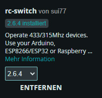
Nachfolgend erläutere ich dir den Aufbau des Quellcodes für eine drahtlose Steuerung des Shelly i4 über einen ESP32. Schritt 1 - einbinden der Bibliothek und definieren der Pins Für den 433 MHz Funkempfänger benötigen wir zusätzlich eine Bibliothek. Hier verwende ich "rc-switch von sui77" welche über den Bibliotheksverwalter installiert werden kann wenn du nach "rc-switch" suchst.
#include // Bibliothek für die 433 MHz Funkkommunikation einbinden // Initialisierung des RCSwitch-Objekts zur Kommunikation mit dem 433 MHz Empfänger RCSwitch rcSwitch = RCSwitch(); // Definition der GPIO-Pins #define remotePin 1 // Empfangs-Pin für den 433 MHz Empfänger #define relais1 2 // Steuerpin für Relais 1 #define relais2 3 // Steuerpin für Relais 2 #define relais3 4 // Steuerpin für Relais 3 #define relais4 5 // Steuerpin für Relais 4 // Definition der Zustände für die Relaissteuerung #define AN true // Relais EIN #define AUS false // Relais AUS Schritt 2 - Konstanten für die Tasten Über das kleine Programm oben habe ich nachfolgende Codes der Tasten ermittelt. Da sich diese Werte nicht ändern habe ich diese in Konstanten abgelegt. // Codes für die 433 MHz Funkfernbedienung (Ein- und Ausschalten der Relais) const long TASTE_1_ON = 83029; const long TASTE_1_OFF = 83028; const long TASTE_2_ON = 86101; const long TASTE_2_OFF = 86100; const long TASTE_3_ON = 70741; const long TASTE_3_OFF = 70740; const long TASTE_4_ON = 21589; const long TASTE_4_OFF = 21588; Schritt 3 - Funktion setup Die Funktion setup wird einmalig aufgerufen wenn der Mikrocontroller startet oder auch neugestartet wird. Hier definieren wir die Pins des Relais Moduls als Ausgang und deaktivieren initial die Relais. void setup() { Serial.begin(9600); // Serielle Kommunikation starten rcSwitch.enableReceive(remotePin); // Aktivierung des 433 MHz Empfängers auf remotePin // Setzen der Relais-Pins als Ausgang pinMode(relais1, OUTPUT); pinMode(relais2, OUTPUT); pinMode(relais3, OUTPUT); pinMode(relais4, OUTPUT); // Alle Relais beim Start ausschalten digitalWrite(relais1, AUS); digitalWrite(relais2, AUS); digitalWrite(relais3, AUS); digitalWrite(relais4, AUS); } Schritt 4 - Funktion loop Die Funktion loop wird dauerhaft ausgeführt bis der Strom abfällt oder ein Fehler auftritt. void loop() { // Prüfen, ob ein Signal vom 433 MHz Handsender empfangen wurde if (rcSwitch.available()) { long remoteValue = rcSwitch.getReceivedValue(); // Empfangenen Code auslesen rcSwitch.resetAvailable(); // Empfangsstatus zurücksetzen Serial.println(remoteValue); // Empfangenen Code zur Diagnose ausgeben //Switch/Case Abfrage } } Schritt 4.1 - Switch / Case für die Tasten Über eine switch Anweisung kann man einfach den empfangenen Wert mit den der Tasten vergleichen. // Überprüfung, ob der empfangene Code einem gespeicherten Befehl entspricht switch (remoteValue) { case TASTE_1_ON: toggleRelais(relais1, AN); break; case TASTE_1_OFF: toggleRelais(relais1, AUS); break; case TASTE_2_ON: toggleRelais(relais2, AN); break; case TASTE_2_OFF: toggleRelais(relais2, AUS); break; case TASTE_3_ON: toggleRelais(relais3, AN); break; case TASTE_3_OFF: toggleRelais(relais3, AUS); break; case TASTE_4_ON: toggleRelais(relais4, AN); break; case TASTE_4_OFF: toggleRelais(relais4, AUS); break; default: Serial.println("Code : " + String(remoteValue) + " nicht behandelt!"); // Fehlermeldung, falls Code unbekannt }
Erweiterte Möglichkeit: Bis zu 8 Geräte mit einem 4-fach Relais steuern
Theoretisch lassen sich mit dieser Schaltung nicht nur vier, sondern bis zu neun verschiedene Geräte steuern – indem man die vier Eingänge des Shelly i4 DC als Bitmuster verwendet.
Shelly i4 DC Wie funktioniert das? - Die ersten drei Eingänge (SW1,SW2, SW3) des Shelly i4 DC werden als Binärcode für die Gerätewahl genutzt. - Der vierte Eingang (SW4) wird als Bestätigungssignal (High-Pegel) verwendet, um die Auswahl auszuführen. Bitmuster für die Geräteauswahl SW1SW2SW3Gerät000Gerät 1001Gerät 2010Gerät 3011Gerät 4100Gerät 5101Gerät 6110Gerät 7111Gerät 8xxxKeine Aktion (SW4 nicht aktiviert) Ablauf der Steuerung - Mit der Funkfernbedienung wird ein 3-Bit-Muster auf die Eingänge SW1-SW3 gesetzt (z. B. „101“ für Gerät 6). - Sobald SW4 auf High gesetzt wird, wertet der Shelly das Bitmuster aus und schaltet das zugewiesene Gerät. - Danach werden alle Eingänge zurückgesetzt, um eine neue Auswahl zu ermöglichen. Vorteile dieser Methode ✔ Erweitert die Steuerungsmöglichkeiten erheblich – statt nur 4 sind bis zu 8 Geräte steuerbar. ✔ Nutzt die vorhandenen Relais effizient – kein zusätzliches Hardware-Modul nötig. ✔ Schnelle und flexible Steuerung – einfach per Funkfernbedienung umsetzbar. Diese Methode zeigt, wie viel Potenzial in der Kombination aus ESP32, Shelly i4 DC und einem 4-fach Relais-Modul steckt! 🚀 Read the full article
0 notes
Text
Arduino Projects
Arduino is a platform for open-source electronics that integrates software and hardware. Its integrated development environment (IDE) and programmable microcontroller board make coding and debugging easier. Its adaptability, affordability, and the vibrant developer community that constantly adds to its ecosystem are the main reasons for its appeal.
Beginner-Friendly Arduino Projects
The traditional "Hello World" of Arduino projects is LED blinking. By programming an LED to blink at various times, you may learn how to control it.
Temperature Monitor: Real-time temperature data are shown on a basic LCD screen using a temperature sensor.
Motion Detector: To build a simple motion-detection system, combine an Arduino board with a PIR sensor.
Components Commonly Used in Arduino Projects
Sensors include motion, light, gas, temperature, and humidity.
Actuators include relays, servos, and motors.
LED, LCD, and OLED displays.
Modules for communication: RFID, GSM, Bluetooth, and Wi-Fi.
Resources to Kickstart Your Arduino Journey
The official Arduino website offers thorough instructions and tutorials.
YouTube Channels: A wealth of detailed video lessons for all abilities.
Forums and Communities: Sites such as Reddit and Arduino.cc offer helpful assistance.
Online courses: Structured learning pathways are available on websites such as edX, Udemy, and Coursera.
Arduino projects are a prime example of ingenuity and originality, enabling people to realize their ideas. Arduino provides countless options for experimentation, learning, and development. regardless of your level of experience. For example, you can study the fundamentals or take on challenging tasks.
Explore the world of Arduino now to realize your creative potential and produce something truly remarkable. Your imagination is the only restriction!
To know more, click here.
0 notes
Text
tbh I just designed the circuits as I went. no schematics we die like men
but I can tell you the parts I used:
Seeed Xiao ESP32C2 microcontroller board
generic single-channel relay module
Meanwell IRM-05-5 DC power supply
momentary button
the basic principle is the microcontroller switches the relay, which powers up the socket and whatever is plugged into it. as a starting point there are lots of tutorials around the internet for controlling a relay with an arduino.
if you try to build one, DO NOT cheap out on the DC power supply for the controller and DO NOT plug it in until everything is fully enclosed in some kind of non-conductive housing. household AC voltage can kill.
I wanted a smart socket to control a table lamp remotely, but I didn't want to a) spend money or b) give 16 global megacorporations detailed information about my lighting habits, so I built this nonsense:

it does the job, and as any millennial can tell you, the transparent casing means it's automatically cool as fuck
452 notes
·
View notes
Text
Proposal for something Awesome [EDITED - v1.1]
Topic: Facial Recognition Door Knob
My proposal for “Something Awesome Project” would be to working on “Facial Recognition Door Lock by using Raspberry Pi”.
Raspberry Pi is a low cost, credit-card sized computer that enables people to create various electronic devices, with a use of high-level programming language (e.g., Python). Ideally, it is possible to integrate it with a simple electronic circuit having relay as a main component to act as a switch to enable the door knob.
I have not had any chance to work on the project that need both software and hardware area before. So I would like to use this opportunity to work in something that I am personally interested in and to push myself forward. Here is my ideas about how it works which could be change due to the development.
With the use of Raspberry Pi (have not been finalised, might change to arduino R3 if it is better), high-level programming can be implemented on it. This can be use as a core of this project to link between facial recognition software and electronic component (door knob).
I would not finalised how the electronic component and circuit design because there are many options to be selected. So in the early state of the design, I might use an LED light to indicate the door knob functionality (for instance light-on: unlock, light-off:lock), then the circuit is going to be designed after the simple model work correctly and here is what I was thinking about in that state.
Relay module is connected into the board, this is going to act as a switch to enable/disable digital output signal which can connected direct to a door knob part.
I personally would like to use it in creating software part by using tensorflow, since I did self-study on it last year and did some simple image processing in converting hand writing into a text but have no experience in any object detection. However, if I could not do it, OpenCV (I have no experience) is my second plan in creating software part.
Planing
I wish to set out the working on my project as follows
Weeks 3: Doing research about facial recognition API and design the circuit.
Weeks 4-6: implementing software part for facial recognition and electronic circuit (with Raspberry Pi, external camera and relay module integrated.)
Weeks 7-8: Unexpected problems and finishing up
Stages and Milestones. [EDITED]
Basic Goals.
Implementing facial recognition software
Creating simple designed electronic model of Raspberri Pi to run the software above
Extension
Uploading progress and demonstration of the facial recognition in each iteration
Writing tutorial and guide on how to build it.
Marking Criteria [EDITED]
Although I have some knowledges about electronic circuits, I have never worked on any practical hardware project before. I could not confidentially ensure that the project would be eventually end up with well-functioned facial recognition uploaded into electronic circuit board that work correctly with the user. So I have created my marking system.
FL - No attempt
PS - Minimal attempt in the project.
CR - Consistent blogs every week in updating what I have done on doing research and how I manage to design the circuit and software implementation.
DN - Either electronic circuit or software is complete but might not work properly (For example, the software works on laptop but not work on the circuit since the different in version or operating system on the board).
HD - The electronic circuit connect to all the component and be able to work with facial recognition software to enable the digital output signal. An extension part is finished.
1 note
·
View note
Text
Arduino Bluetooth Controlled 4CH Switch Tutorial
Arduino Bluetooth Controlled 4CH Switch Tutorial
1. Circuir Diagram of Arduino Bluetooth Controlled 4C Switch 2. Code Program Arduino Copy code program below to arduino IDE project /* Relay IN1 connected to PinOut 2 Arduino Relay IN2 connected to PinOut 3 Arduino Relay IN3 connected to PinOut 4 Arduino Relay IN4 connected to PinOut 5 Arduino --->you can connected to relay modul 4 channel Serial data sending from Arduino Bluetooth Relay…

View On WordPress
0 notes
Link
Recomended Products

Component listing: 1pcs UNO R3 Controller Board 1pcs LCD1602 Module ( with pin header) 1pcs Breadboard Expansion Board 1pcs Power Supply Module WARNING: Pls. do not use the voltage higher than 9V 1pcs Joystick Module 1pcs IR Receiver 1pcs Servo Motor (SG90) 1pcs Stepper Motor 1pcs ULN2003 Stepper Motor Driver Board 1pcs Ultrasonic Sensor 1pcs DHT11 Temperature and Humidity Module 1pcs 9V Battery with DC 1pcs 65 Jumper Wire 1pcs USB Cable 1pcs Active Buzzer 1pcs Passive Buzzer 1pcs Potentiometer 1pcs 5V Relay 1pcs Breadboard 1pcs Remote 1pcs Tilt Switch 5pcs Button (small) 1pcs 1 digit 7-segment Display 1pcs 4 digit 7-segment Display 5pcs Yellow LED 5pcs Blue LED 5pcs Green LED 5pcs Red LED 1pcs RGB LED 2pcs Photo resistor 1pcs Thermistor 2pcs Diode Rectifier (1N4007) 2pcs NPN Transistor (PN2222) 1pcs IC 74HC595 120pcs Resistor 10pcs Female-to-male DuPont Wire. Free PDF tutorial(more than 22 lessons) and clear listing in a nice package Free PDF tutorial(more than 22 lessons) and clear listing in a nice package The most economical kit based on Arduino platform to starting programming for those beginners who are interested. Free PDF tutorial(more than 22 lessons) and clear listing in a nice package Free PDF tutorial(more than 22 lessons) and clear listing in a nice package The most economical kit based on Arduino platform to starting programming for those beginners who are interested. Lcd1602 module with pin header (not need to be soldered by yourself) Free PDF tutorial(more than 22 lessons) and clear listing in a nice package Free PDF tutorial(more than 22 lessons) and clear listing in a nice package The most economical kit based on Arduino platform to starting programming for those beginners who are interested. Free PDF tutorial(more than 22 lessons) and clear listing in a nice package Free PDF tutorial(more than 22 lessons) and clear listing in a nice package The most economical kit based on Arduino platform to starting programming for those beginners who are interested. Lcd1602 module with pin header (not need to be soldered by yourself) This is the upgraded starter kits with power supply module, 9V battery with dc Free PDF tutorial(more than 22 lessons) and clear listing in a nice package Free PDF tutorial(more than 22 lessons) and clear listing in a nice package The most economical kit based on Arduino platform to starting programming for those beginners who are interested. Free PDF tutorial(more than 22 lessons) and clear listing in a nice package Free PDF tutorial(more than 22 lessons) and clear listing in a nice package The most economical kit based on Arduino platform to starting programming for those beginners who are interested. Lcd1602 module with pin header (not need to be soldered by yourself) Free PDF tutorial(more than 22 lessons) and clear listing in a nice package Free PDF tutorial(more than 22 lessons) and clear listing in a nice package The most economical kit based on Arduino platform to starting programming for those beginners who are interested. Free PDF tutorial(more than 22 lessons) and clear listing in a nice package Free PDF tutorial(more than 22 lessons) and clear listing in a nice package The most economical kit based on Arduino platform to starting programming for those beginners who are interested. Lcd1602 module with pin header (not need to be soldered by yourself) This is the upgraded starter kits with power supply module, 9V battery with dc High quality kite with UNO R3. 100% compatible with Arduino UNO R3, MEGA 2560 R3, NANO.
0 notes
Text
Temp and Humidity Alert Using AWS and ESP32

In this tutorial, we will measure different temperature and humidity data using Temp and humidity sensor. You will also learn how to send this data to AWS.
Hardware
ESP-32: The ESP32 makes it easy to use the Arduino IDE and the Arduino Wire Language for IoT applications. This ESp32 IoT Module combines Wi-Fi, Bluetooth, and Bluetooth BLE for a variety of diverse applications. This module comes fully-equipped with 2 CPU cores that can be controlled and powered individually, and with an adjustable clock frequency of 80 MHz to 240 MHz. This ESP32 IoT WiFi BLE Module with Integrated USB is designed to fit in all ncd.io IoT products. Monitor sensors and control relays, FETs, PWM controllers, solenoids, valves, motors and much more from anywhere in the world using a web page or a dedicated server. We manufactured our version of the ESP32 to fit into NCD IoT devices, offering more expansion options than any other device in the world! An integrated USB port allows easy programming of the ESP32. The ESP32 IoT WiFi BLE Module is an incredible platform for IoT application development. This ESP32 IoT WiFi BLE Module can be programmed using the Arduino IDE.
IoT Long Range Wireless Temperature and Humidity Sensor: Industrial Long Range Wireless Temperature Humidity Sensor. Grade with a Sensor Resolution of ±1.7%RH ±0.5°C. Up to 500, 000 Transmissions from 2 AA Batteries. Measures -40°C to 125°C with Batteries that Survive these Ratings.Superior 2-Mile LOS Range & 28 miles with High-Gain Antennas.Interface to Raspberry Pi, Microsoft Azure, Arduino and More
Software Used
Arduino IDE
AWS IoT
Library Used
PubSubClient Library
Wire.h
AWS_IOT.h
Uploading the Code to ESP32 using Arduino IDE
Download and include the PubSubClient Library and Wire.h Library.
Download the Zip file of AWS_IoT, from the given link and after extracting, paste the library in your Arduino library folder.
You can get the Arduino code here.
You must assign your unique AWS MQTT_TOPIC, AWS_HOST, SSID (WiFi Name) and Password of the available network.
MQTT topic and AWS HOST can get inside Things-Interact at AWS-IoT console.


Compile and upload the ESP32_AWS.ino code.
Before uploading the code add a certificate inside the AWS_IOT folder to aws_iot_certficates.c, which is done in further steps.
To verify the connectivity of the device and the data sent, open the serial monitor. If no response is seen, try unplugging your ESP32 and then plugging it again. Make sure the baud rate of the Serial monitor is set to the same one specified in your code 115200.
Serial Monitor Output

Making the AWS Work
youtube
Create Thing and Certificate
THING: It is a virtual representation od your device.
CERTIFICATE: Authenticates the identity of a THING.
Open AWS-IoT
Click on manage -THING -Register THING.
Click on create a single thing.
Give the Thing name and type.
Click on next.
Now your certificate page will open, click on Create Certificate.
Download these Certificates, mainly private key, a certificate for this thing and root_ca and keep them in a separate folder.
Inside root_ca certificate click on Amazon root CA1-Copy it-Paste it to notepad and save it as a root_ca.txt file in your certificate folder.
Create Policy
youtube
It defines which operation a device or user can access.
Go to the AWS-IoT interface, Click on Secure-Policies.
Click on Create.
Fill all the necessary details such as policy name, Click Create.
Now go back to the AWS-IoT interface, Click on Secure-Certificates and attach the policy created just now to it.
Add Private key, Certificate and root_CA to Code
Open your downloaded certificate in your text editor(Notepad++), mainly private key, root_CA and certificate of thing and edit them as the format of aws_iot_certficates.c inside AWS_IOT folder.
Now open your AWS_IoT folder in your Arduino library -My Document. Go to C:\Users \xyz\Documents\Arduino\libraries\AWS_IOT\src, click on aws_iot_certficates.c, open it on an editor and paste all the edited certificate their at the required place, save it.


Getting Output
youtube
Go to test in the AWS_IoT console.

Fill your MQTT topic to Subscription topic in your test credentials.

Now you can view your temp and humidity data.
Output

Steps to Make Mail Alerts
youtube
You set up Amazon Simple Notification Service (Amazon SNS) for creating mail alert to receivers address for different temperature and humidity readings.
Go to AWS IoT console -Click on Act.
Don't have any rule -Click on create a rule.
On this page Name the rule i.e AlertTempEsp32, also provide the description(Creating mail alert of Temp and Humidity sensors data).
Now create Rule Query Statement(SQL statement for processing data from source).In this the statement used is
SELECT*FROM'$aws/things/Temp_Humidity_esp32/shadow/update'
$aws/things/Temp_Humidity_esp32/shadow/update, Go to AWS IoT Console -Manage-Thing-Click on your created Thing -Interact.
To choose an action Click on ADD Action.
Select send a message as an SNS push notification.
Now Configure Action selected. for SNS target-choose Create. Enter a name for the SNS topic, such as Temp_Humidity_Esp32Topic.Message Format -Raw. Create role -Temp_Humidity_Esp32TopicRole.
Add Action.
Create a rule.
Create Amazon SNS to send the messages through your Amazon SNS topic to your email inbox. Click on Services.
youtube
Search SNS. Click on SNS.
In Amazon SNS -Click on Subscription. Select the topic ARN.Protocol-Email -Give your email Address on which alert to be sent.
Now click on Create Subscription.
After clicking the Create Subscription. You have to confirm Subscription by clicking on the mail, that is sent to your registered mail ID.

Confirm Subscription link.

OUTPUT

0 notes
Text
Wemos D1 mini Shield: Relais Shield

In diesem Tutorial möchte ich das Relais Shield für den Wemos D1 mini vorstellen.

Relais Shield für den Wemos D1 mini Ein Relais Shield habe ich bereits im Tutorial Arduino Lektion 13: 2 fach Relaisplatine ansteuern beschrieben. Dieses Shield funktioniert im Grunde genauso nur halt das dieses Shield "nur" 1 Relais Modul enthält.
Bezug
Das Relais Shield kann über ebay.de oder amazon.de bezogen werden. Wobei auch hier wieder das Shield zum besten Preis bei ebay.de erhältlich ist.
Technische Daten des Relais Shield für den Wemos D1 mini
- max. 10A bei 250V AC (Wechselspannung) - max 10A bei 30V DC (Gleichspannung)
Aufbau und Anschluss
Das Relais Shield wird wie die anderen Shields auf den Wemos D1 mini gesteckt. Hier bietet es sich an, sich ein Dual Base Shield zu besorgen. Denn das Relais Shield hat bedingt durch die Bauhöhe des Relais keine Möglichkeit ein weiteres Shield auf dieses zu stecken.

Relais Shield + One Button Shield auf dem Dual Base Shield
Quellcode
Das Relais Shield wird über den digitalen Pin D1 angesprochen (Hinweis dazu ist auf der Rückseite des Shields bzw. auf der Wikiseite zum Shield zu finden.) #define RELAIS D1 //Relais Shield am digitalen Pin D1 angeschlossen #define BUTTON D3 //One Button Shield am digitalen Pin D3 angeschlossen void setup() { pinMode(BUTTON,INPUT); //Den Button als Eingangssignal definieren. pinMode(RELAIS,OUTPUT); //Das Relais als Ausgangssignal definieren. } void loop() { /* * Wenn der Button gedrückt wird, dann wird das Relais angezogen. * D.h. es wird das Relais aktiviert, das aktivieren ist deutlich am klick Geräusch * zu hören und wird optisch durch eine LED angezeigt. */ digitalWrite(RELAIS, digitalRead(BUTTON)==HIGH?LOW:HIGH); } Read the full article
1 note
·
View note
Text
Arduino Projects
Both a physical programmable circuit board (microcontroller) and software (Arduino IDE) are components of Arduino, which is used to develop and upload code to the board. From basic LED blinkers to complicated home automation systems, the platform can handle a broad variety of tasks. It is a well-liked option for makers all around the world because of its user-friendly interface, robust community support, and cost.
Why Choose Arduino for Your Projects?
Easy to Use: Arduino is suitable for both novices and experts because of its straightforward hardware connections and user-friendly IDE.
Accessible and Inexpensive: Arduino boards and parts are readily accessible and reasonably priced.
Huge Community Support: The learning curve is accelerated by having access to forums, tutorials, and an extensive collection of shared projects.
Compatibility: To increase project functionality, Arduino supports a large variety of sensors, actuators, and shields.
Exciting Arduino Project Ideas
Beginner Projects
Intermediate Projects
Advanced Projects
Components Required for Arduino Projects
Arduino Boards: Nano, Mega, or Uno models.
Sensors include those for motion, light, gas, temperature, and soil moisture.
Actuators include relays, motors, and servos.
LCD, OLED, or LED screens are examples of displays.
Bluetooth, Wi-Fi, or GSM modules are examples of connectivity modules.
Other: resistors, capacitors, jumper wires, and breadboards.
Arduino and STEM Education
In STEM (science, technology, engineering, and mathematics) education, Arduino is a vital instrument. It gives students practical learning opportunities while teaching them electronics, coding, and problem-solving techniques. Arduino projects are incorporated into the curricula of many colleges and institutions in order to promote technical proficiency and creativity.
For both professionals and enthusiasts, Arduino projects offer a plethora of opportunities. You can build critical technical abilities and realize your creative ideas by investigating different applications. Arduino's extensive community and limitless resources make it possible for anybody to explore the exciting fields of programming and electronics.
So take out your Arduino board, let your imagination run wild, and get to work creating something incredible right now!
To know more, click here.
0 notes
Text
[Something awesome] iteration #6 [FINAL]
This is my last blog about my awesome project. There were so many problems happened along the way before I finished this blog. My Raspberry Pi got bricked 3 hours after I had finished integrating hardware and software components together. So I had no chance to record the video of it.
I spent fully 2 and days to reinstall the and set things up in my spare raspberry pi (As I mentioned in #5.5). However, it did not turn out as I had expected. Raspbian Buster, the latest version of the raspberry pi operating system, created for Raspberry Pi 4 which is the new model, is not 100% compatible with my model B+ and causes so many trouble while installing OpenCV module which takes 2-3 hours each time. It kept ending with error installation around 88-100% of the installation. I tried 5 different versions of this module (3.4, 3.4.1, 3.2.0, 4.0.0, 4.0.1) but all of them failed. I felt kind of regret that I did not take a video of my project before it got brick.
Fortunately, Last night at 3am, I decided to move on and looking for a way to make my software run in Arduino UNO in order to have some simulation to be shown in the presentation. Thanks to my Thai electrical engineering friend that guided me through this. So apart from how to do GPIO programming in python (for Raspberry Pi), I would write about how to control Arduino UNO through pyFirmata (module for python3) as another extension that was not mentioned in the proposal.
Redesigned Circuit

This is my new circuit connection. One more LED diode has been added and move the 5V DC source to NC side of the relay module. This would make the circuit to have 2 led color that can indicate door being locked or unlocked.
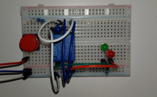
This is what it looks like in the real connection. It becomes way cleaner than the previous one having very messy wires and jumpers.

The green light indicates that the door is unlocked, while red is the opposite way.
GPIO programming for Raspberry Pi
Example of GPIO programming on Raspberry Pi
After I have both software and hardware prepared good enough to be put together, the time that I have been waiting for so long is here!
Let’s put them together and create a really cool facial recognition doorknob system. What I have to do is just set the digitalWrite signal to enable the relay module once my face is detected.
Firstly, the GPIO module is needed if this software is going to run on Raspberry Pi. It basically allows you to access all the pin on the board.
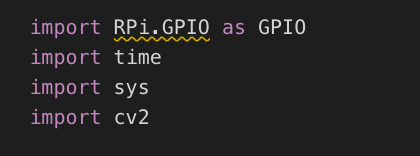
Next step is about to pick one pin as an output. The code below takes care of that.
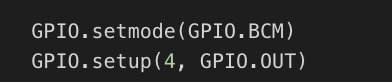
Then add a couple line of codes to make the pin to send digital output to the GPIO port in our circuit. A new code including line 22, 23, 41, and 50 to 55. It is very basic logic.
pyFirmata programming for Arduino UNO
This section is an additional one from having bricked Raspberry Pi. It is just to test that software and hardware can run together correctly because all of the computational parts are done by the laptop connected to Arduino. So the board is basically just a tool to send a digital signal to the circuit, no computation stuff at all.

So a module taking care of controlling the output pin in this time is pyFirmata. To do this you need to upload a standard program of Firmata into the Arduino board.

Arduino software provides you this program. You do not even have to learn how to code about this. PyFirmata is a program that changes your Arduino, that usually perform a software part, this burden is pushed to the high-level programming side (python in this time). So we can do everything, for example, reading and writing the pins.

The codes above have to be added into the main program of the recognition. It just specifies the port address connecting to the board, sets input and output pins.
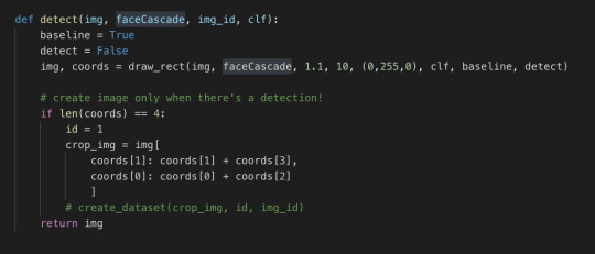
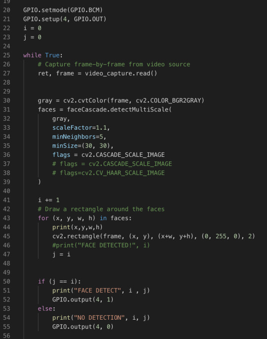
The first method is the detect. It is almost exactly the same as in iteration #5. The only difference is that I changed i and j into the boolean flags.
This is pretty much the same as last iteration’s code as well. Lines 28 to 32 are added. Just only 4 lines of code, we can have our system run on Arduino UNO! Isn’t it cool?
Running the program!
After all the time I spent on this project, this is the moment I have been waiting for. The facial recognition system that I created myself, got out of my comfort zone to build it from the scratch and researched heaps of self-learning. This video below could describe everything.
Video of the final result
Conclusion
This is a very long journey for me. I have learned a lot and my perspective of computer vision technology has been completely changed as well. I was really excited and proud of myself in the presentation today when I tested my program and shown it in the class. The reaction of everyone in the tutorial class made me feel like all the hard work paid off. Although my ways of explaining things are not that good, I hope you enjoy my blog and can gain at least some new knowledge from it. Cheers!
0 notes
Text
Designing and building our RFID Lock Box
In thinking about bringing a technical puzzle to our piece, I decided to embark on building a RFID Lock Box.
Components:
Arduino UNO
RFID Sensor (MFRC522)
Relay Module
Solenoid Lock
Buzzer
LEDs
Some jumper cables.
The way it works is it uses a solenoid lock and RFID module connected to an Arduino. A player would need to scan the correct UID key to unlock the box to access its contents. If the correct key is scanned, a green LED is triggered, if the wrong key is scanned, the player will hear a buzzer and a red LED will be triggered.
Below is schematic showing how the circuit works.


Once, the circuit was built. I did a quick mock up of the physical design of the box to house the circuit. It took a while to work out the best way to build the lock mechanism.

A prototyping process took place to work out the correct dimensions of the physical parts that made the box.
I first attempted to take accurate measurements of the components using a vernier caliper and made some sketches. Then using Adobe Illustrator and a laser cutter at our hatch labs, I first laser cut using cardboard to make adjustments to the measurements until they were perfect. Finally, laser cutting the box using clear acrylic.


I put together a short video outlining the design and development process of building the lock box in more detail.
youtube
Code provided below

If I have more time, I would like to add a function to allow the buzzer to play different melodies to the player based on the UID key scanned. I found a useful guide on this here.
I enjoyed putting this puzzle together and can’t wait to see it in action when we begin play testing our piece.
References
Arduino Projects Book, 3rd Edition, May 2015 - Scott Fitzgerald, Michael Shiloh and Tom Igoe
https://howtomechatronics.com/tutorials/arduino/rfid-works-make-arduino-based-rfid-door-lock/
- Bobby
0 notes
Text
Creative Process.
Physical computing
I began the project with very little knowledge of physical computing, therefore I adopted an exploratory and iterative process in creating the outcome. Upon purchasing an Arduino starter kit, I began to work through basic LED and relay tutorials.

Once getting a relay circuit running with a 5v motor, I purchased a larger 12v DC vacuum pump to prototype with. I chose a 12v motor because of its higher litres per minute air flow rating – I wanted a large and obvious bubbling effect. However, this meant moving onto using an external power supply unit which I found difficult to wire initially. I had to understand the difference between the horizontal power and ground rails, and the vertically oriented circuit area, as well as the schematics for the components in order to wire them so power could flow correctly. After purchasing a 12v battery pack (8 x 1.5v AA batteries) and wiring the 12v motor with the relay, I began to research the ways in which I could map sensor input values to motor speed. I was initially confused, wondering how I could use a 5v PWM signal to power a 12v motor. I came across motor drivers while searching through forums and realised I had a couple included inside the Arduino starter kit. Wiring this was the next challenge – I had to again figure out the functions of each pin on the motor driver chip, and how they corresponded to the digital output pins on the Arduino. I referenced the lastminuteengineers.com guide (https://lastminuteengineers.com/l293d-dc-motor-arduino-tutorial/) for both wiring and programming this. The next step was to wire in an FSR – I used an adafruit guide (https://learn.adafruit.com/force-sensitive-resistor-fsr/using-an-fsr) for this, using a 10Kohm resistor and wiring it into the Arduino’s 5V power rail on the breadboard. I used the same tutorial to figure out how to program the Arduino so it could read and output the FSR input values to the serial monitor. I could then work out how I needed to map each value for motor driver PWM. The FSR input values were between 0 and 1023, so I mapped them to the motor power bounds of 40 to 255 – I used 40 as the minimum map value because I wanted the motors to pump even when little pressure was applied. I then added a threshold of a force of 50 to accommodate for sensor interference – the FSR never read a value of zero and fluctuated around the 20’s when no pressure was applied. I initially ran into problems using pulse width modulation, with the motor behaving strangely. I realised this was because I was using digital output pins that weren’t PWM compatible – I had to switch the analogWrite pins to ones that had a tilda next to them on the board (pins 3, 5, 6, 9, 10, 11). After achieving my desired interface between motor and FSR, the next stage was to scale up by adding two more motors and FSRs. I was initially unsure whether I’d have to use millis() and a control system to ‘multitask’, and referenced these tutorials (https://www.embeddedcomputing.com/application/industrial/motor-control/designing-control-systems-with-multiple-motors and https://learn.adafruit.com/multi-tasking-the-arduino-part-1/ditch-the-delay), however after discovering this (https://youtu.be/dyjo_ggEtVU) youtube tutorial, I realised it could be done without millis or delay. This made the programming much simpler.

0 notes
Text
Monitoring-Temp-and-Humidity-using-AWS-ESP32

In this tutorial, we will measure different temperature and humidity data using Temp and humidity sensor. You will also learn how to send this data to AWS.
Hardware :
ESP-32: The ESP32 makes it easy to use the Arduino IDE and the Arduino Wire Language for IoT applications. This ESp32 IoT Module combines Wi-Fi, Bluetooth, and Bluetooth BLE for a variety of diverse applications. This module comes fully-equipped with 2 CPU cores that can be controlled and powered individually, and with an adjustable clock frequency of 80 MHz to 240 MHz. This ESP32 IoT WiFi BLE Module with Integrated USB is designed to fit in all ncd.io IoT products. Monitor sensors and control relays, FETs, PWM controllers, solenoids, valves, motors and much more from anywhere in the world using a web page or a dedicated server. We manufactured our own version of the ESP32 to fit into NCD IoT devices, offering more expansion options than any other device in the world! An integrated USB port allows easy programming of the ESP32. The ESP32 IoT WiFi BLE Module is an incredible platform for IoT application development. This ESP32 IoT WiFi BLE Module can be programmed using the Arduino IDE.
IoT Long Range Wireless Temperature And Humidity Sensor: Industrial Long Range Wireless Temperature Humidity Sensor. Grade with a Sensor Resolution of ±1.7%RH ±0.5° C.Up to 500,000 Transmissions from 2 AA Batteries.Measures -40°C to 125°C with Batteries that Survive these Ratings.Superior 2-Mile LOS Range & 28 miles with High-Gain Antennas.Interface to Raspberry Pi, Microsoft Azure, Arduino and More
Long-Range Wireless Mesh Modem with USB Interface
Software Used:
Arduino IDE
AWS
Library Used:
PubSubClient Library
Wire.h
AWS_IOT.h
Uploading the code to ESP32 using Arduino IDE:
Download and include the PubSubClient Library and Wire.h Library.
Download the Zip file of AWS_IoT, from the given link and after extracting, paste the library in your Arduino library folder.
You must assign your unique AWS MQTT_TOPIC, AWS_HOST, SSID (WiFi Name) and Password of the available network.
MQTT topic and AWS HOST can get inside Things-Interact at AWS-IoT console.
Compile and upload the ESP32_AWS.ino code.
To verify the connectivity of the device and the data sent, open the serial monitor. If no response is seen, try unplugging your ESP32 and then plugging it again. Make sure the baud rate of the Serial monitor is set to the same one specified in your code 115200.
Serial monitor output.

Making the AWS work.
CREATE THING AND CERTIFICATE
THING: It is a virtual representation od your device.
CERTIFICATE: Authenticates the identity of a THING.
Open AWS-IoT


Click on manage -THING -Register THING.
Click on create a single thing.

Give the Thing name and type.

Click on next.

Now your certificate page will open, Click on Create Certificate.

Download these Certificates, mainly private key, a certificate for this thing and root_ca and keep them in a separate folder.

Inside root_ca certificate click on Amazon root CA1-Copy it-Paste it to notepad and save it as a root_ca.txt file in your certificate folder.

Create Policy
It defines which operation a device or user can access.
Go to the AWS-IoT interface, Click on Secure-Policies.

Click on Create.

Fill all the necessary details such as policy name, Click Create.
Now go back to the AWS-IoT interface, Click on Secure-Certificates and attach the policy created just now to it.


Add Private key, Certificate and root_CA to code.
Open your downloaded certificate in your text editor(Notepad++), mainly private key, root_CA and certificate of thing and edit them as given below.

Now open your AWS_IoT folder in your Arduino library -My Document. Go to C:\Users \xyz\Documents\Arduino\libraries\AWS_IOT\src, click on aws_iot_certficates.c, open it on an editor and paste all the edited certificate they're at the required place, save it.
Getting Output-
Go to test in the AWS_IoT console.

Fill your MQTT topic to Subscription topic in your test credentials.

Now you can view your temp and humidity data.
OUTPUT

0 notes
Text
ArduinoTutorial 97: Solid State Relais

In diesem Beitrag möchte ich das Solid State Relais (kurz "SSR") vorstellen. Des Weiteren möchte ich auch auf die Unterschiede zwischen einem "normalen" und einem Solid State Relais eingehen.

Solid State Relais Mit einem Solid State Relais kann man eine Wechselstromquelle schalten. D.h. wir können nicht so einfach eine LED oder andere mit Gleichstrom betriebene Aktoren steuern.
Bezug
Das Solid State Relais gibt es wie auch die "normalen" Relais Module in verschiedene Ausführungen (einfach, 2fach, 4fach, 8fach). Die Preise sind auch sehr gut dem "normalen" angeglichen daher lohnt sich meiner Meinung nach die Anschaffung dieses SSR mehr als einem "normalen" Relais. Auf ebay.de kann man die SSRs schon ab ca. 1,36€ inkl. Versandkosten (aus China) erwerben, wenn man mehr die deutschen Shops unterstützen möchte so muss man etwas tiefer in die Tasche greifen (ca. 4,99€ inkl.Versandkosten), hat dann aber eine deutlich bessere Lieferzeit. Ich habe auf mein Relais knapp 2 Monate gewartet, dieses nehme ich gerne in kauf wenn die Bauteile für Tutorials erwerbe, wenn ich jedoch die Bauteile für ein Projekt benötige so bestelle ich schon mal im Inland.
Aufbau
Ein SSR ist vom Aufbau komplett anders als ein "normales" Relais. Schauen wir uns einmal zunächst das SSR an und dann ein "normales" Relais. Solid State Relais Das Solid State Relais (im folgenden nur noch als SSR benannt) besteht aus 2 Schaltkreise welche durch eine galvanische Schicht voneinander getrennt sind.

Aufbau eines Solid State Relais Durch diese zwei Schaltkreise entfallen wie bei einem "normalen" Relais die beweglichen Teile und somit können diese bei schnellen Schaltvorgängen nicht "verkleben". Ablauf Wenn die LED eingeschaltet wird, wird dieses durch einen Fotowiderstand registriert und dieses schaltet wiederum den Triac bzw. MOSFET (kurzform von "Metall-Oxid-Halbleiter-Feldeffekttransistor"). "normales" Relais

2fach Relais Modul für den Arduino Ein "normales" Relais besteht aus beweglichen Kontaktfedern welche durch das aktivieren einer Spule (anlegen einer Spannung) zusammen gedrückt werden. Wenn man nun die Spannung von der Spule wieder entnimmt so trennen sich die Kontaktfedern.

Aufbau eines normalen Relais mit einer Spule Problem bei schnellen Schaltvorgängen Wenn man nun sehr sehr schnell das Relais aktiviert und deaktiviert so kann es passieren das die Kontaktfedern verkleben, d.h. durch die entstehenden Ströme kleben diese zusammen.
Anschluß des Solid State Relais an einen Arduino
Das SSR Modul verfügt über eine 3fach Schraubklemme welche auf der Vorderseite mit "DC+", "DC-" sowie "CH1" gekennzeichnet sind. Solid State Relais Arduino DC+ 5V DC- GND CH1 digitaler Pin D2
Schaltung
In der nachfolgenden Schaltung verwende ich eine 230V Stromquelle. Beachte immer die 5 Regeln im Umgang mit Spannungen > 24V: Freischalten Gegen Wiedereinschalten sichern, Spannungsfreiheit allpolig feststellen, Erden und kurzschließen, Benachbarte, unter Spannung stehende Teile abdecken oder abschranken
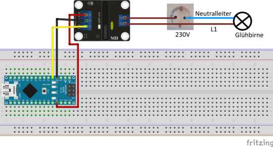
Aufbau der Schaltung - Solid State Relais am Arduino Nano mit einer 230V Glühbirne
Quellcode
Da das Relais über einen einfachen digitalen Eingang verfügt welchen wir lediglich auf HIGH bzw. LOW setzen müssen um den Zustand zu ändern ist das Programm doch sehr übersichtlich. #define relais 2 const int PAUSE = 2500; void setup() { pinMode(relais, OUTPUT); } void loop() { digitalWrite(relais, HIGH); delay(PAUSE); digitalWrite(relais, LOW); delay(PAUSE); }
Video
Fazit
Ein Solid State Relais ist gut geeignet um eine Wechselstromquelle zu schalten und als Ersatz für ein "normales" Relais. Jedoch kann man mit diesem nur Wechselstromquellen schalten und ist nicht so universell einsetzbar wie ein "normales" Relais. Es entfällt auch das lästige klicken beim einschalten des Relais. Read the full article
0 notes
Video
youtube
Tutorial stm32f4 relay control
================== Please subscribe our channel, thanks For modification please contact us, thanks Please visit, thanks Entertainment for Engineer's break time Rixtronix LAB Channel https://www.youtube.com/channel/UC89se0BZ2oGeqN5jNbDAyQQ Rixtronix LAB is looking for local engineering bussiness partner, please contact us, thanks Rixtronix LAB 正在寻找当地工程业务合作伙伴,请与我们联系,谢谢 Please share a coffee with me, thanks... Motherboard Capacitors 1800uF 16V low ESR https://www.ebay.com.au/itm/173840921403 Motherboard Capacitors 1000uF 16V low ESR https://www.ebay.com.au/itm/173841745704 Arduino Uno R3 Brand NEW https://www.ebay.com.au/itm/173828695857 Arduino Mega 2560 Brand NEW http://www.ebay.com.au/itm/173846013344 7812 Regulator Chip 12V TO-220 http://www.ebay.com.au/itm/173840902816 7805 5V Voltage Regulator 10 Pieces http://www.ebay.com.au/itm/173373792576 MC34063 DC-DC converter control circuits DIP8 5Pcs http://www.ebay.com.au/itm/173840921443 1N5822 Diode 10pcs 3A 40V Fast Recovery Schottky diode https://www.ebay.com.au/itm/174166491028 3D Printer Melzi 2.0 1284P Mainboard PR Usa 1Pcs http://www.ebay.com.au/itm/173831753941 3D Printer LCD Module 20x4 1Pc https://www.ebay.com.au/itm/173838265965 Mechanical Watch 6 hands Automatic 1Pcs https://www.ebay.com.au/itm/173840921415 Rixtronix Store,electronic components,3D Printer Parts and electronic modules https://www.ebay.com.au/str/rixtronix Please donate for buying my children's milk, thanks http://PayPal.Me/rixtronix Tapped Spacer M3x25 5Pcs https://www.ebay.com.au/itm/173841750164 STM32L011 Nucleo 32 https://www.ebay.com.au/itm/173846014737 3D Printed Look Keo Cleat Thicker Hook Areas 1pair, I've tested for more than 1 year ride https://www.ebay.com.au/itm/173910460603 Rixtronix LAB is looking for local engineering bussiness partner, please contact us, thanks Rixtronix LAB 正在寻找当地工程业务合作伙伴,请与我们联系,谢谢 Rixtronix LAB Log https://rixtronixlab.blogspot.com/ https://rixtronix.joomla.com/ https://bianchi77.wordpress.com/ ==================
0 notes